
ACC DEVICE INSTALLATION
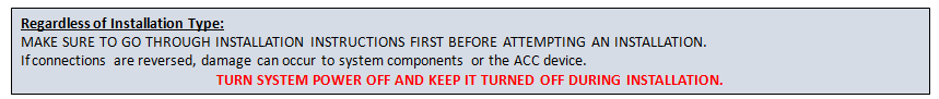
IMPORTANT
PLEASE READ STEPS BEFORE INSTALLING THE ACC DEVICE
Visit www.coilws.com or contact Vendor for Technical Support
SECTION A: PRECHECK SYSTEM AND LAYOUT PREFERED ENTIRE INSTALLATION PROCESS
BEFORE INSTALLING:
1. PLEASE READ ALL STEPS BEFORE INSTALLING THE ACC DEVICE AND REFER TO ANY OTHER MANUALS OR SECTIONS AS NEEDED.
2. CHECK PACKAGE CONTENENTS
- CHECK MANUALS AND PROVIDED PAPER SLIPS to follow indications and ensure all material is present.
- CHECK OVERALL MATERIAL IN PACKAGING: make sure it is correct, complete and undamaged.
- CHECK ANY CONNECTORS AND CABLES: make sure provided adapters, and sensors are the right fit. Inspect that all cables provided are in good working condition.
3. HAVE ALL THE TOOLS NEEDED FOR THE PARTICULAR INSTALLATION TYPE
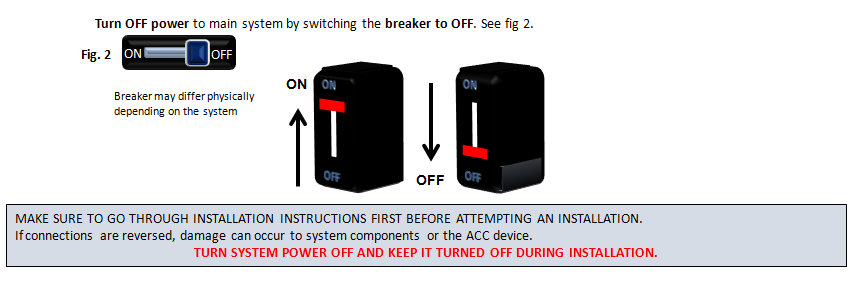
4. ALWAYS TURN OFF POWER TO THE SYSTEM. DO NOT INSTALL ACC DEVICE IN LIVE CIRCUITRY! TURN OFF ANY POWER SOURCE INVOLVED WITH THE INSTALLATION!
5. Take Notes, and Pictures or make Sketches of the circuitry involved in the system. This is to help and refer to particular conditions when following installation process.
STEP 1A:
Check general package contents.
See fig 1.
Visual Inspection
- Open Open ACC Device package
- Examine the content to make sure all components are present and undamaged
*Content may differ per specified model
NOTE: The installation is to be performed in accordance with ALL necessary safety regulations by qualified service personnel only.
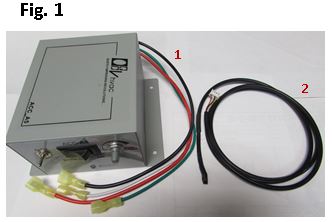
Package List
1) ACC Device with 4 Power Wires
2) Temperature Cable (4 Pin Cable)
STEP 1B:
BEFORE DOING ANY CHANGES. Ensure the entire system is operational and working properly.
Ensure the entire system is operational and working properly. Make sure it contains a compatible motor. Contact vendor for further information if needed.
- Find out of any special functions, or features that may be interfered by the ACC device.
Refer to its operation manuals as necessary. See the following general guidelines:
1. Clear out anything that may obstruct inspection and future installation process.
2. Check to see that HVAC Unit can reach set point and cycles; it shuts OFF and turns ON as expected.
3. Check if temperature control or any other signal control units involved with the system are working as expected.
4. Measure system AC Line Voltage and verify good AC ground
5. Measure voltage to the fan motor.
6. See if there is enough space to prepare ACC device placement, and installation.
7. Prepare a location where the temperature sensor will be set.
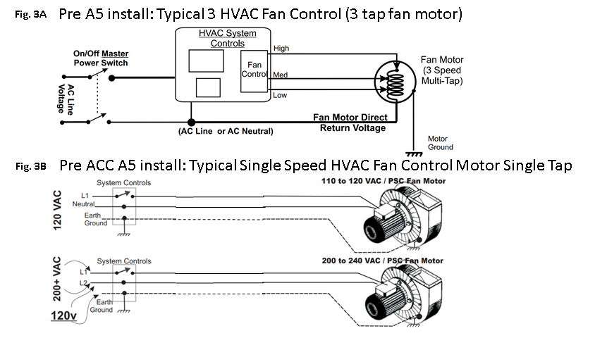
AFTER EXAMINING ORIGINAL SYSTEM SETTINGS AND CONFIGURATION.
Inspect current installation, and original wiring of the system. Make notes, draw sketches or take pictures of original system wiring.
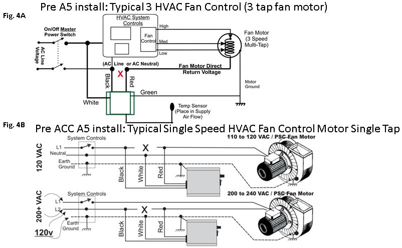
See fig 3 for examples of a typical electrical configuration of a fan motor.
Examine and analyze original wiring of the system. Make notes, draw sketches or take pictures of original system wiring.
See fig 4 for examples of a typical electrical configuration when an ACC device is introduced in the system
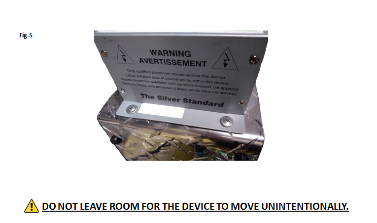
Examine and analyze placement of the ACC device. Make sure it fits and that that wiring can be configured securely. Physically make sure it can be attached, screwed, and fit snug (stays in place) in a location during the installation process.
See fig 5 as an example.
SECTION B: Installation Process. Refer to previous notes, pictures, or sketches to determine connection to and from the device.
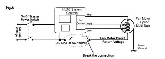
Examine and analyze original wiring of the system. Disconnect (cut / interrupt) usual single direct AC line feed (return voltage) to fan motor.
See fig 6.
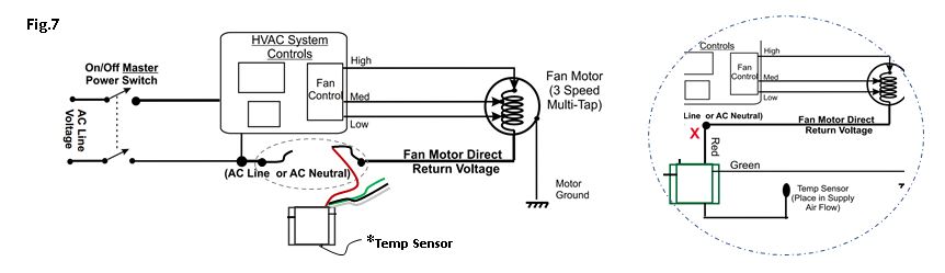
Examine and analyze wiring of the system. Connect the RED cable from the ACC device to the fan wire motor side of the broken connection.
See fig 7.
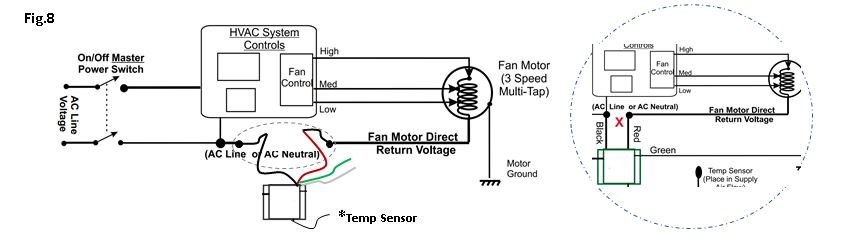
Examine and analyze wiring of the system. Connect the BLACK cable from the ACC device to AC power line of the other side of the broken connection.
See fig 8.
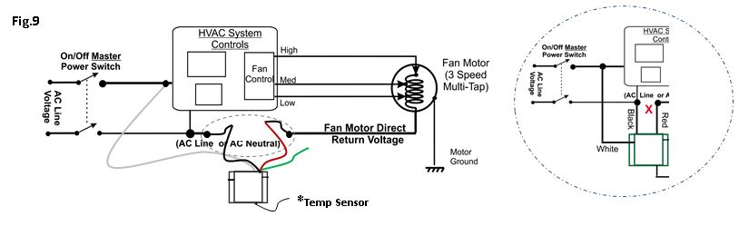
Examine and analyze wiring of the system. Connect the WHITE cable from the ACC device to the opposite AC power line.
See fig 9.
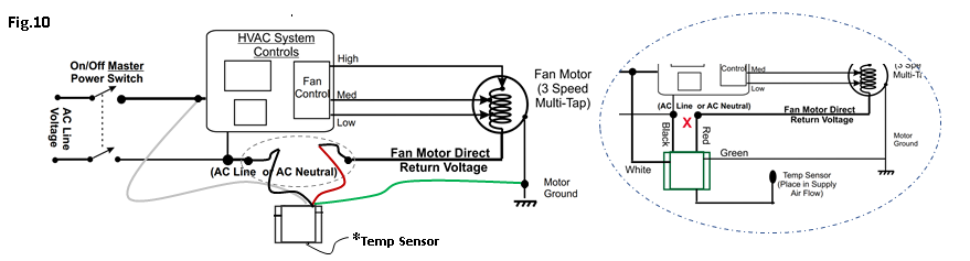
Examine and analyze wiring of the system. Connect the GREEN cable from the ACC device to EARTH/PHYSICAL (NEUTRAL) GROUND (must always have good 0 voltage ground).
See fig 10.
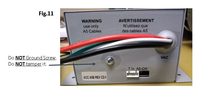
Examine and analyze wiring of the system. Connect a cable to the chassis of the ACC device to EARTH/PHYSICAL GROUND if needed.
See fig 11. DO NOT GROUND OR TAMPER WITH ANY SCREWS
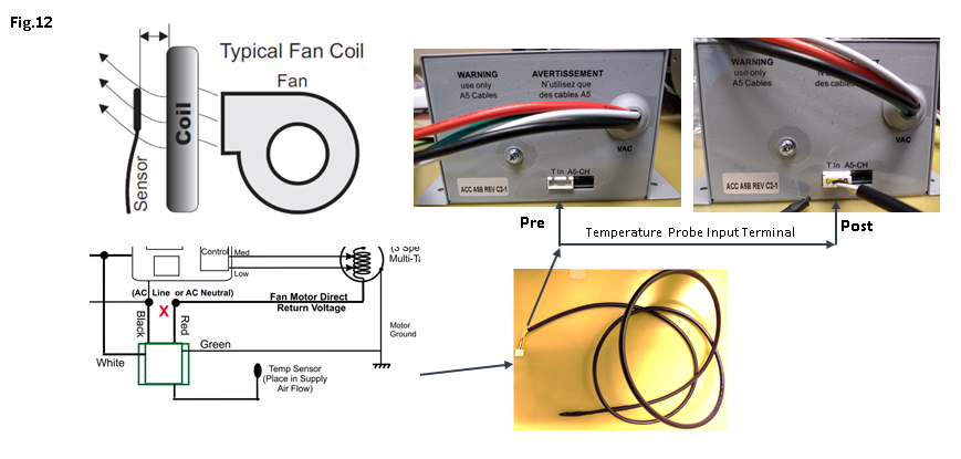
Examine Space around the connections. The temperature probe is to be placed in the Discharge / Supply Air Stream area (where there’s good air flow).
Locate sensor where the Proper Air Temperature was measured Prior to Upgrade.
Make sure this cable probe is secured, stays in place and does not become dislodged.
For cooling: Supply Air Temperature Sensor location must be 55 degree Fahrenheit or lower.
For heating: Supply Air Temperature Sensor location must be 100 degree Fahrenheit or higher.
See fig 12 for probe connection
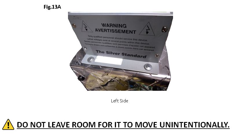
Examine and analyze placement of the ACC device. Make sure it fits and that that wiring can be configured securely. Physically make sure it can be attached, screwed, and fit snug (stays in place) in a location during the installation process.
AFTER INSPECTING: PLACE AND TIGHTLY SCREW THE ACC DEVICE IN THE BEST LOCATION.
See fig 13 as an example.
SECTION C: POST CHECK OF SYSTEM AND ACC DEVICE BEHAVIOR
AFTER INSTALLATION CHANGES.Make sure all wiring and connections are correct.
- Check if there are any loose connections in the entire system to make sure it is operational and that it will work properly.
- Find out of any special functions, or features that may be interfered by the ACC device.
- Go through all the previous installation steps to check that electrical connections are correct and organized.
Refer to operation manuals as necessary. See the following general guidelines:
1. Clear out anything that may obstruct inspection.
2. Reconnect any wiring that may have been disconnected on purpose, and is needed for the system to function correctly.
3. Make sure the ACC Device is held stable and in place (to prevent sudden and unwanted movement).
4. Make sure the temperature probe is in a convenient position to measure BEST Output Air temperature
5. Make sure the temperature probe is in held in place (not movable) and will not interfere with anything in the system.
6. Check to see that HVAC Unit can reach set point and cycles; it shuts OFF and turns ON as expected.
7. Check if temperature control or any other signal control units involved with the system are turned OFF and unchanged.
8. Measure system AC Line Voltage and Good AC Ground connect.
9. Measure voltage to the fan motor.
AFTER CHECKING THAT WIRING AND SYSTEM CONNECTIONS ARE CORRECT FOR OPERATION.
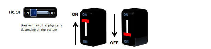
Turn ON power to main system by switching the breaker to ON.
See fig 14.
AFTER RESTORING POWER TO THE SYSTEM. CHECK VOLTAGE AND SYSTEM OPERATION
Refer to operation manuals as necessary. See the following general guidelines:
1. Measure system AC Line Voltage:
- Voltage between BLACK and WHITE cables of the ACC device always equals FULL AC Line Voltage.
- Voltage between RED and WHITE cables of the ACC device VARIES from AC Line Voltage down.
- Voltage between BLACK or WHITE cables of the ACC device and its GREEN cable always equals AC Line to AC Ground.
2. Measure voltage to the fan motor
3. Run a test in the system with ACC device in Bypass selection
4. Run a test in the system with ACC device in ON selection and with the switch indicating the Manual option.
5. Run a test in the system with ACC device in ON selection and with the switch indicating the AUTO option.
Set the system to the default options and place back anything that was removed during installation that will not interfere with the system.
Leave a note or take a picture for future technical reference as necessary.